

Using an Adafruit NeoTrellis Keypad with MQTT

I’ve been building a light-up keypad for home automation devices (and Zoom sessions). Last time, I gave an overview of the project. This entry will detail the hardware itself, completing a basic remote-only setup, while the next post adds more advanced features and connects it to a server. You can browse the entire series from the link in the header, or by clicking here.
Hardware
I spent some time trying to find just the right hardware for this toy. I looked at USB keyboards, custom keyboards from the performance driving world, video editing keyboards, and even some fancy systems with little color LCD displays on each key. I ended up picking the 4x4 NeoTrellis Kit from Adafruit.
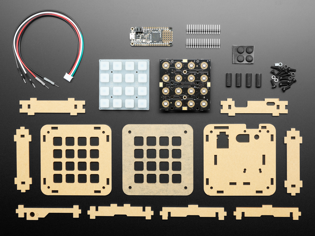
Adafruit 4x4 NeoTrellis Feather M4 Kit Pack
It comes with:
- Feather M4 Express (microcontroller) with header pins & connector cable
- 4x4 silicone keypad buttons
- 4x4 NeoTrellis keypad board
- Laser-cut acrylic case with hardware and feet
The whole thing, today, costs $45.95. Not bad, given what it can do. Unfortunately, they were out of stock, but I was able to purchase from their partners at DigiKey, and it arrived within a few days.
The included microcontroller doesn’t support Wi-Fi, so I move to a SparkFun Thing Plus - ESP32 Wroom. I’ve been using these with some other projects and had extras already on the shelf, though eventually I plan to move back to the board that came with the kit.
Anyway, I connected the four wires in the cable to my I2C bus (SDA - data, SCL - clock, and of course, power and ground). I assembled the case, plugged it in, downloaded the Arduino libraries, and installed one of the example programs. It worked! I can now hit buttons and they light up. In different colors, no less.
Initial Problems
But it wasn’t perfect. I ran into some problems with the initial examples, but I wasn’t sure why. Maybe because they were designed for a different controller board?
First, I wanted to write my firmware in MicroPython. I had used that for a different project, and it seemed a natural choice for the keypad. But the library I need for the keypad only supports CircuitPython. And CircuitPython isn’t supported on the Thing Plus. I briefly considered copying just the minimum code needed, but there was simply too much. So I stuck with the basic Arduino C environment.
Making things more complicated, I had Wi-Fi issues. Turns out, there’a a Mac Mini bug when the USB3 ports are in use, causing Wi-Fi and Bluetooth interference. This is super frustrating, especially because I frequently can’t use the serial debug console. Sometimes it works great for a solid hour, while other times, it fails right off and remains broken for the rest of the evening. Switching to a Wi-Fi network with a closer access point seemed to help, but it still failed frequently. Nevertheless, I kept plugging on…
A Quick Digression About MQTT
MQTT stands for “Message Queueing Telemetry Transport.” Aside from using one of the very few English words with five consecutive vowels, what does this thing do? It’s a simple protocol used to send short messages over slow or unreliable networks. Devices can subscribe to “topics” – basically, you tell the server “tell me anytime you pass a message about <this>.” And then other devices publish messages to those topics.
So I can send the message “FF0000” to “controller/keypad/light/5”, and any device which subscribes to that topic will see the message. What they do with it is up to them. In my case, my keypad will turn the light under key #5 to bright red.
MQTT is used extensively in home automation, and is the underpinning for my whole system. This is how my keypad will send signals to my computer, and how other controllers will control its lights.
Setting Up As A Basic MQTT Device
So back to my keypad. I’d like to start with a basic proof-of-concept: key presses send messages, and other messages change the color of the lights. There’s not much to it, really. The program basically looks like this:
- Setup:
- Initialize the keypad
- Connect to Wi-Fi, and then to the MQTT server
- Subscribe to a topic for inbound light-change messages
- Establish routines that get called when:
- A message comes in: change a light
- A key is pressed: send a message
- Loop, and listen for keyboard and MQTT events
Fortunately, the hard parts (Wi-Fi, setting up MQTT, etc.) are easily borrowed from example code, and the easy parts are, well, very easy. I’ve put the whole source code in this GitHub gist, but for now, these are the important bits.
Note: it’s not pretty code. I’m not much of a C programmer, and I’m still new at MQTT and am probably not building my topic hierarchy quite “right.” Excuses made, now let’s see how it works.
First, the function that processes inbound MQTT messages. I’m looking for a message like “controller/keypad/srvr/light/5”:
void onMqttMessage(char* topic, char* payload, AsyncMqttClientMessageProperties properties, size_t len, size_t index, size_t total) {

  if (! strncmp(topic, "controller/keypad/srvr/light/", 29)) {
      char *ptr = topic;
      ptr += 29;
      int light_num = atoi(ptr);

      long int rgb = strtol(payload, 0, 16);
      byte red = (byte)(rgb>>16);
      byte green = (byte)(rgb>>8);
      byte blue = (byte)(rgb);

      trellis.pixels.setPixelColor(light_num, red, green, blue);
  }

  trellis.pixels.show();
}
First, I check that the message topic, or subject, starts with controller/keypad/srvr/light. Using a new character pointer ptr, I jump forward 29 characters, past the base of the topic, and read the rest of the string as an integer. That gives me the number of the light that’s being changed. Then I take payload, which is the message itself, and interpret it as a hexadecimal number. So FF00FF gets turned into a long integer, which is then shifted around to extract the red, green, and blue components. Finally, I send the received pixel color to the NeoTrellis LED array, and refresh it with trellis.pixels.show().
There’s really no validation going on here. If either the light or the color isn’t a valid number, then they end up with zeros, and the worst that happens is the first button goes dark. Actually, the worst that happens is the whole thing just reboots, or more rarely, hangs. More on some of that later.
The second function is used to briefly blink the keys as they’re pressed, and pretty much comes straight from the Adafruit example. When you press the key, the signal generated at the chip goes high, so it’s “rising.” Even though the key itself is being pressed down. (It is what it is.) Anyway, if you’ve just pressed the key, then the event “EDGE” is set to rising, and we change the button’s light to white.
If the button is being released, then we change the color back to black, and send an MQTT message to controller/keypad/srvr/key/N, where N is the key number (0-15). The message is just the one word “pressed.” Not very original, but whatever.
TrellisCallback blink(keyEvent evt){
  uint16_t packetIdPub1;

  if (evt.bit.EDGE == SEESAW_KEYPAD_EDGE_RISING) {
    trellis.pixels.setPixelColor(evt.bit.NUM, 255, 255, 255);

  } else if (evt.bit.EDGE == SEESAW_KEYPAD_EDGE_FALLING) {
    trellis.pixels.setPixelColor(evt.bit.NUM, 0);

    char cmd[64];
    snprintf(cmd, 64, "controller/keypad/srvr/key/%d", evt.bit.NUM);
    packetIdPub1 = mqttClient.publish(cmd, 1, false, "pressed");
  }
  trellis.pixels.show();

  return 0;
}
So now, we can send messages when a key is pressed, and handle commands to change the color of individual keys. Neat!
New Problems
This example code works great – we push a button, and it lights up. The remote control even works…most of the time. I wrote a simple python program to change the color of each key in turn, and…about 30% of the time, the messages aren’t processed. Also, every now and then the whole thing just reboots. What gives?
Initially, I suspected the I2C bus connecting the keypad to the microcontroller. The problem only occurred with inbound MQTT messages, and I thought that the WiFi transmitter was creating noise on the circuit. So, I added delays inside onMqttMessage. That didn’t help. Then I added pull-up resistors, as used with other I2C projects. Finally, I disabled the keyboard scan part of the program – and the problem went away! Weird, huh?
Here’s what’s happening (as best as I can tell). The program has a main loop that scans the keyboard, waits for a second, then repeats. Again, taken directly from the Adafruit example code:
void loop() {
  trellis.read();  // interrupt management does all the work! :)

  delay(20); //the trellis has a resolution of around 60hz
}
This is the main core of the program. I don’t actually have to explicitly call the function to process inbound messages, because the MQTT library does that for me.
If I comment out trellis.read(), the problem goes away. Why? Because if I receive a message while I’m scanning the keyboard, then control jumps into onMqttMessage, which tries to write a new pixel color to the keypad. If we were already in the middle of reading from the keypad…then things get messed up, and neither the key-press nor the command are properly handled.
I didn’t notice any keyboard problems, because no matter how quickly I hit the button, it’s closed for much longer than 0.02 seconds. The key just gets read on the next journey through the loop. But once interrupted, the MQTT message is gone, forever, and the light won’t change color. Sometimes, things get so out of whack that it crashes, and the whole thing hangs or reboots.
Dropping the read() function means the conflict never occurs, and so it works perfectly. If I change the delay from 20 mS to 100 mS…then the problem seems (mostly) to go away. It’s a big improvement, but again, it’s pretty likely that any key-press is going to last more than 1/10 of a second, so I can live with the trade-offs.
Further Improving Performance
Though this helps, I still occasionally get drop-outs where a light doesn’t change color, or where the keypad crashes. I tried pulling just the trellis.pixels.show() call out of the MQTT processing function, and while that helped a little, it still wasn’t enough. I ended up moving all trellis library calls out of onMqttMessage and into the main loop.
I imagined a queue of light change requests, processing them all in bulk. But really, there’s no point in keeping two different changes to the same light, right? Since the second change would overwrite the first, and we’re talking about small fractions of a second. So I set up an array of long int numbers, and whenever the high bit is set, I read the lower three bytes as red, green, and blue values and reset the pixel to that color.
Here are the various bits of code (shown as one snippet for clarity):
long int new_light_colors[16];

void setLight(int light, int r, int g, int b) {
  new_light_colors[light] = 0x80000000 | (r<<16) | (g<<8) | b;
}

void setLightHex(int light, long int rgb) {
    new_light_colors[light] = 0x80000000 | rgb;
}

// [.....]

void loop() {
  long int rgb;
  byte c, r, g, b;

  trellis.read();

  for (int i=0; i<16; i++) {
    rgb = new_light_colors[i];
    r = (byte)(rgb>>16);
    g = (byte)(rgb>>8);
    b = (byte)(rgb);

    if (rgb & 0x80000000) {
      trellis.pixels.setPixelColor(i, r, g, b);
      new_light_colors[i] = 0;
    }
  }
  trellis.pixels.show();

  delay(100);
}
Now, anywhere that I had trellis.pixels.setPixelColor(), is changed to setLight(), and all trellis.pixel.show() calls are deferred until we get back to the main loop. I wrote a simple python program to send a new color to each pixel, one pixel at a time, and was able to get down to 125 mS (1/8 of a second) with virtually no drop-outs. While this was happening, the keypad was still able to process key-press events. It even worked reasonably well at 62.5 mS, but it wasn’t great. So I think I’m pretty happy with this approach.
Ideally, I’d take the time to verify that the conflict really is happening in the Trellis library and fix the bug, but for my purposes, this will probably be Good Enough.
I should still add some error checking and trapping, to maybe catch when things go bad and avoid reboots (or at least, avoid a hang). The nice thing about controlling the lights over MQTT, is that as long as messages are sent with a “retain” flag, then the device will fetch the last few changes after reboot and return itself to its prior state. So even if it does crash and reboot, aside from seeing a fancy start-up animation out of the corner of my eye, I may never know that it had happened.
Again, the complete source code for this “minimal mqtt” implementation is available on GitHub.
What’s Next?
Though the keypad is now “fully functional,” there are still some enhancements I can add to make it a little easier to work with. We’ll cover that in the next post, and then I’ll talk about actual end devices.